Oct 26, 2026Guide
How Stainless Steel Assemblies Are Split into Fabrication-Friendly Components
Where to break a stainless steel assembly into components: polish access, weld distortion, transport limits and site adjustment all drive the split.
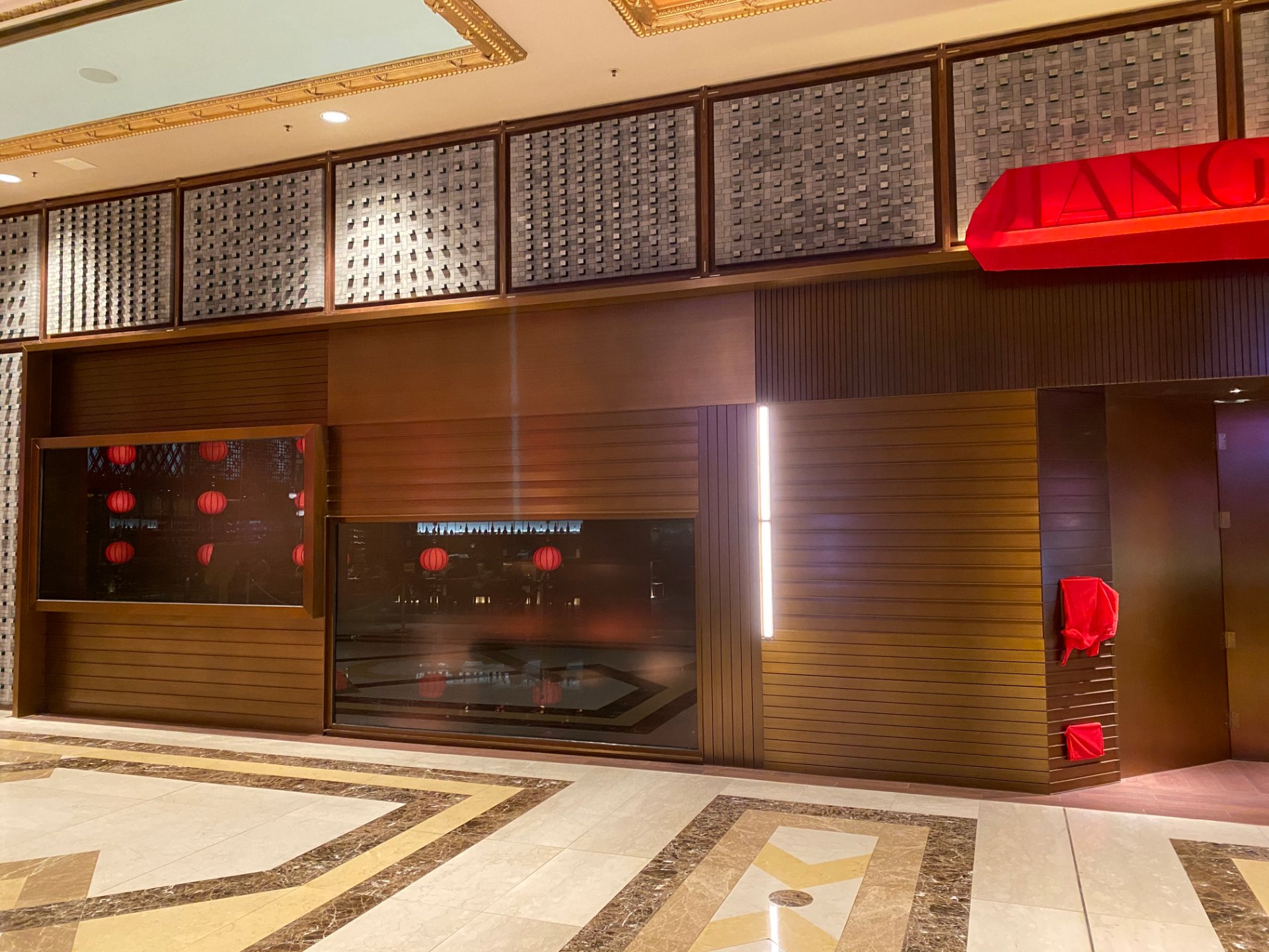
On drawings, a stainless steel counter, screen or wall cladding looks like one continuous object. In the workshop it never is. Every architectural metalwork assembly has to be split into components that can be polished, welded, transported and installed — and where that split happens has a bigger effect on cost and final quality than almost any other fabrication decision.
For designers and fit-out contractors, understanding the logic behind component splits makes shop drawing reviews faster and helps explain why a fabricator proposes joints where the design shows none.
Why the Split Matters More Than the Material
Stainless steel is forgiving to cut and form but demanding to finish. A mirror or hairline finish must be applied after welding and grinding, and every polish needs physical access to the surface. A detail that looks clean on paper — a fully enclosed return, a deep recessed channel — can be impossible to polish to spec once it is welded up.
Splitting the assembly correctly solves four problems at once:
- Polish access — every finished face must be reachable with polishing tools before assembly.
- Weld distortion — heat pulls thin-gauge stainless; shorter weld runs on smaller components keep faces flat.
- Transport — oversized one-piece fabrications cost more to crate and risk damage in transit.
- Site installation — components must pass lifts, doorways and corridor turns, and allow final adjustment on site.
Typical Split Points
Corners and returns. The most common split is at external corners. A 90-degree corner can be formed from one sheet, but for thick or heavy sections it is usually made as two components joined at the corner, with the weld ground and polished into the radius.
Reveal joints. Where the design allows a shadow gap or reveal, the split is placed inside it. Two panels meeting in a 10 mm reveal hide their joint completely, and neither piece needs post-weld blending on the visible face.
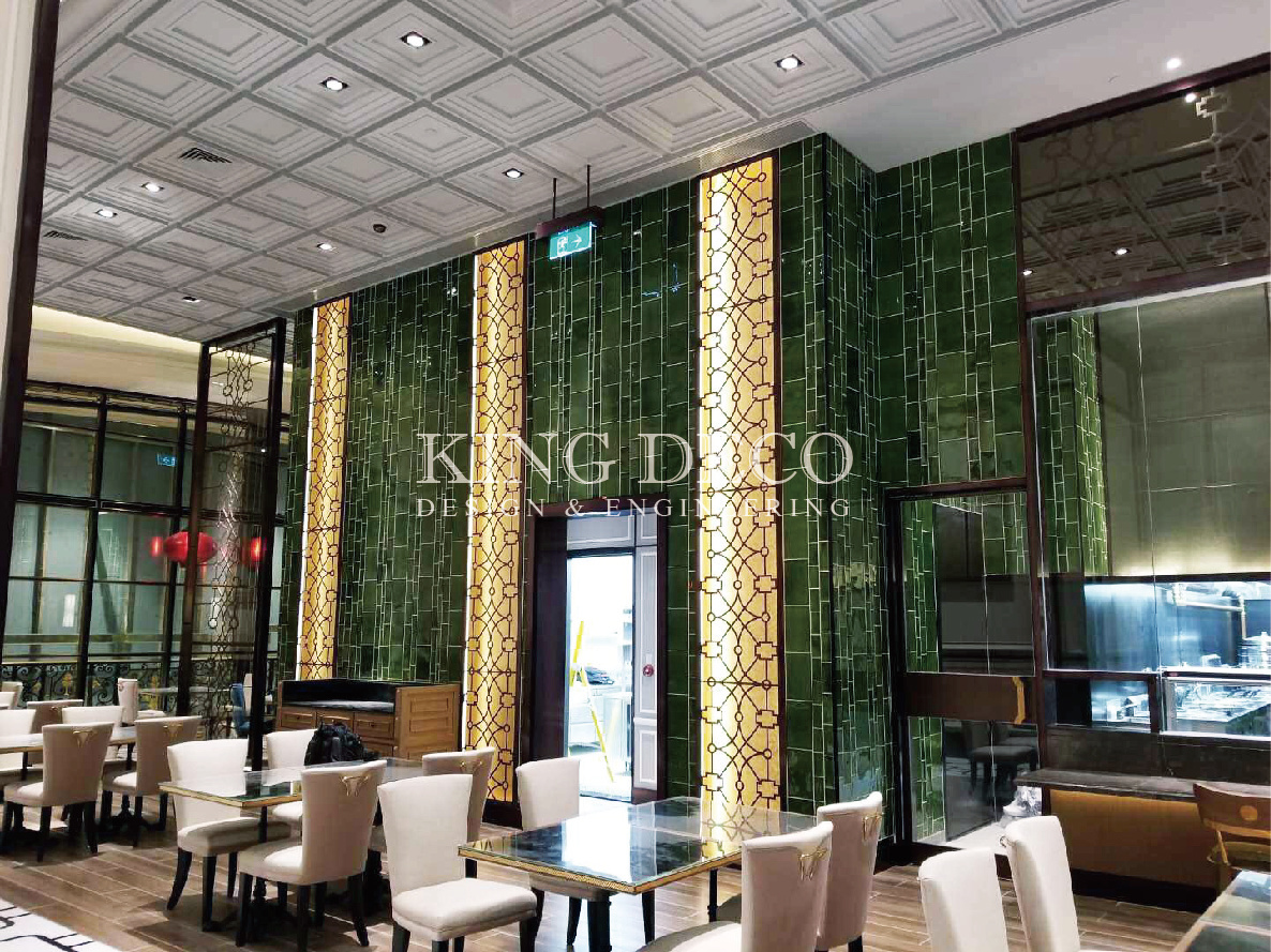
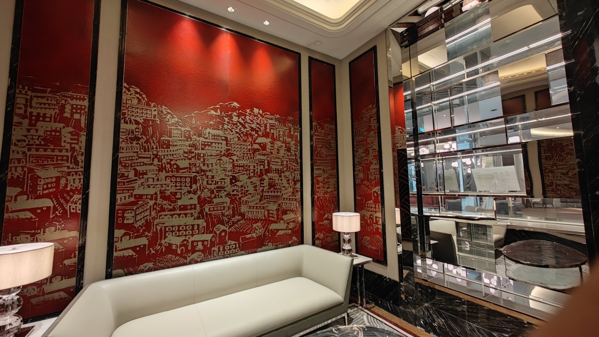
Panelized cladding. Large wall and ceiling surfaces are divided into panels sized for polishing tables, crates and handling — commonly in the 1.2 to 2.4 m range depending on the system. Panelization also localizes any distortion: one panel that moves in the weld can be reworked without touching its neighbours.
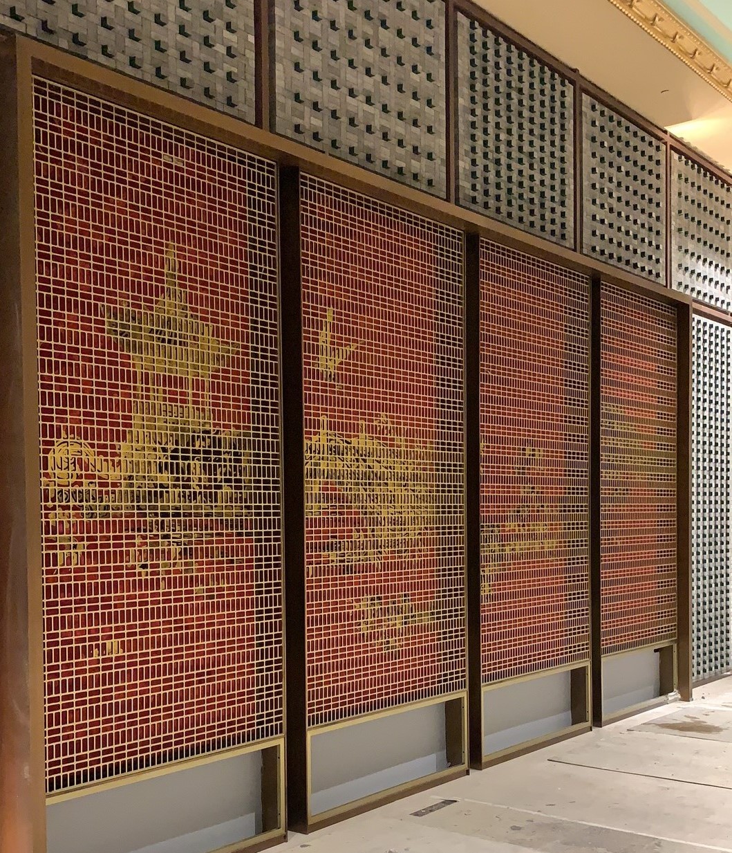
Screen and balustrade modules. Decorative screens are split into modules at verticals or frame members. This keeps each module light enough for two-person handling and allows a damaged module to be replaced without dismantling the run.
Choosing the Seam Strategy
Once the split location is decided, the joint itself has three basic strategies:
Weld and polish. The joint is welded, ground and re-finished so the assembly reads as one piece. This is the premium look, and the standard for hotel and casino feature metalwork where seams would otherwise catch the eye. It costs the most because every seam needs skilled finishing — and it is only possible where the polisher can reach the joint.
Mechanical fix. Components are screwed, bolted or fixed with concealed brackets. The seam stays visible as a deliberate line, which works well when the design already expresses a grid or module. Mechanical joints allow disassembly, which matters for long runs installed floor by floor.
Shadow gap. The components meet with a small intentional gap, often with a dark backing. This is the most tolerant joint: it absorbs site tolerance, thermal movement and minor misalignment without any visual penalty. On projects with tight programmes, moving splits into shadow gaps is one of the fastest ways to de-risk installation.
On hospitality projects we usually combine all three on the same assembly — weld-and-polish on hero faces, mechanical fix where maintenance access is needed, shadow gaps where the base or abutment meets other trades.
Tolerance and Site Adjustment
A split assembly is also an adjustment strategy. Site dimensions are never exactly the drawing dimensions, so fabricators leave adjustment in at least one joint per assembly: slotted fixing holes, adjustable feet, or a cover trim that spans a variable gap.
When reviewing shop drawings, the useful questions are:
- Where does each assembly measure against site, and where can it grow or shrink?
- Which seams are weld-and-polish, and are they all accessible in the workshop?
- How is each piece transported and handled — weight, dimensions, protection?
- Who sets out the fixing points, and what tolerance does the substrate carry?
A fabricator who answers these in the shop drawing set has usually built the assembly before. One who sends back a single monolithic detail for everything has probably not.
What the Fabricator Needs from Your Drawings
The split is ultimately a joint decision. Designers do not need to draw every seam, but the design should indicate:
- Finish locations — which faces are mirror, hairline or PVD, because finishes dictate polish access and therefore where splits must fall.
- Acceptable joint expression — whether seams must disappear or can be part of the language of the piece.
- Fixed dimensions — full-height glass abutments, stone rebates and openings that cannot move.
Everything else can be developed in the shop drawing round, which is exactly what that stage is for.
Working It Through
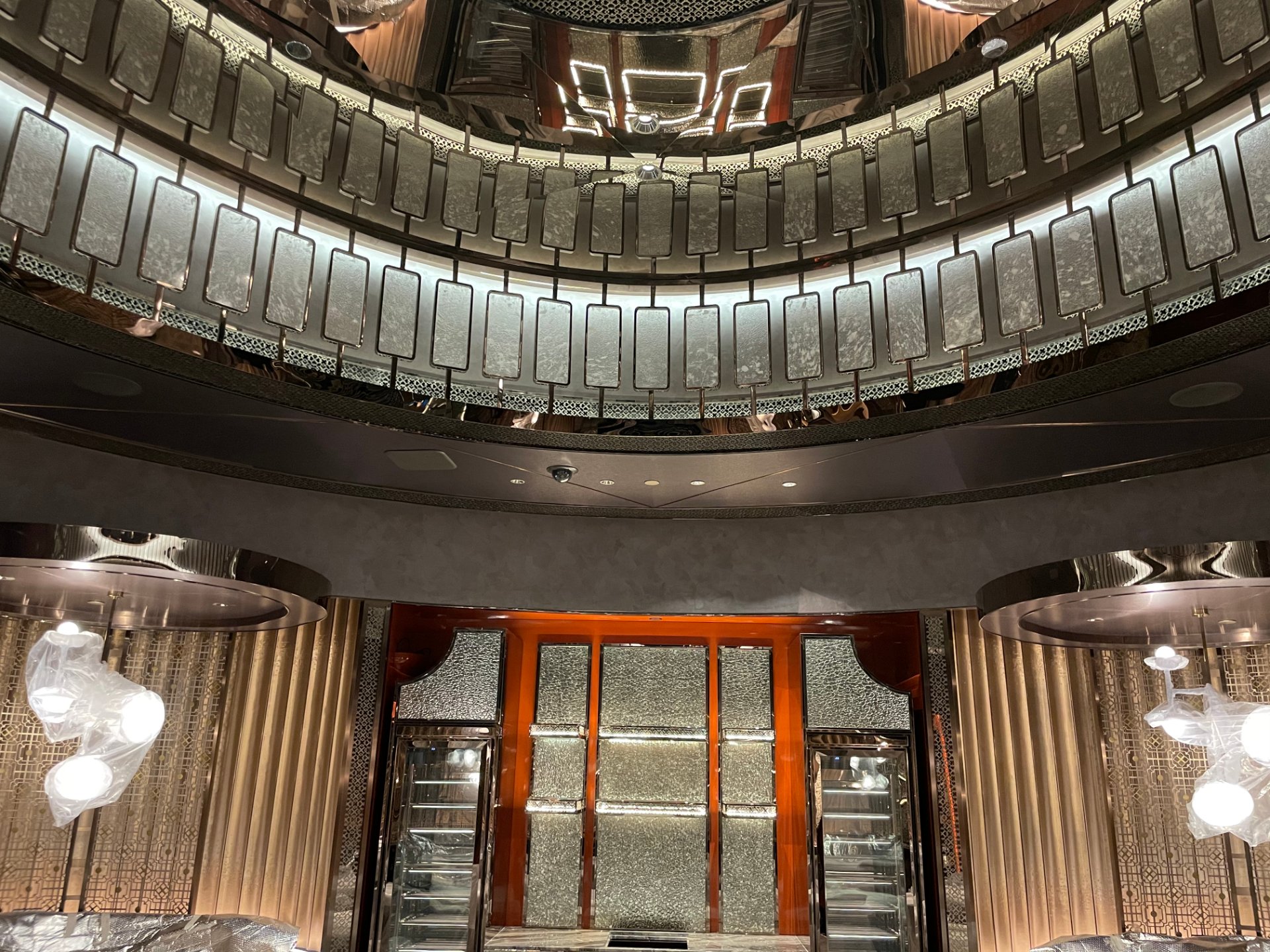
On hospitality and casino projects in Macau — from MGM Cotai to Galaxy and The Venetian — most of the metalwork packages we supply were split, seam-mapped and tolerance-planned long before the first sheet was cut. That early work is invisible in the finished space, which is the point: the assembly reads as one continuous piece of metal, and the site team installs it in pieces that actually fit.
If you are developing a stainless steel package and want a fabrication view on where it should split, send the design drawings across and we will mark up the seams, finishes and access points before you commit to shop drawings.